This page describes how to modify the wind sensor of a La Crosse WS2300 Weather
Station.
The modification was done based on hints I have received both from
La Crosse, Richard Huntington (New Zealand) and my own experiments.
Many
trials have been made and this modification is the only one that has worked
for me so far.
The La Crosse WS2300 (and WS2305, WS2310) have a problem with the wind sensor. If the cable between wind sensor and outdoor temperature/humidity sensor is exposed to electromagnetic interference the wind sensor reading often becomes 25.5 m/s or 91.8 km/h.
The impedance level between the wind sensor and the temperature/humidity sensor is kept pretty high to save battery power. Obviously the design is not as robust as it could have been. But there is a reasonably easy modification that can be done without being very technically skilled.
The modification requires the following tools
The following material is needed
The category 5 STP cable is assumed to have 4 twisted pairs colours, blue/blue-white,
brown/brown-white, yellow/yellow-white and green/green-white.
If the cable
you use has different colours you will have to convert the colours. You could
probably use normal shielded cable with 3 wires, but the STP cable is easy to
get in a computer store and the wire gauge will fit the modular 6P4C connector
perfectly. The STP cable I have used has a metal foil shield and an additional
thin shield wire that runs along the metal foil.
The modification is in essence replacing the unshielded and untwisted cable between wind sensor and outdoor temperature/humidity sensor by a shielded cable and additionally take advantage of the twisted pairs and pair the 3 signal/power wires with a ground wire for additional noise immunity.
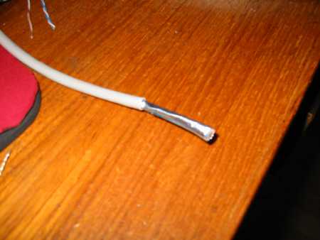
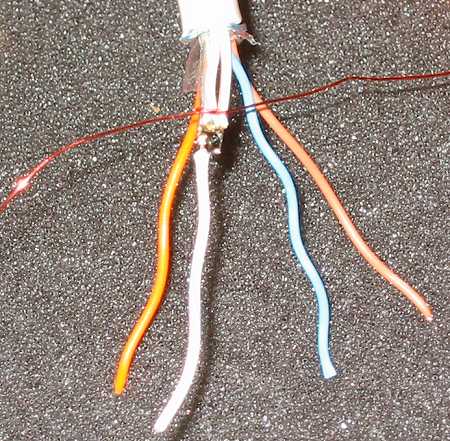
We start at the end of the outdoor temperature/humidity sensor.
Step 1. Remove the outside isolation. Remove roughly 40-50 mm.
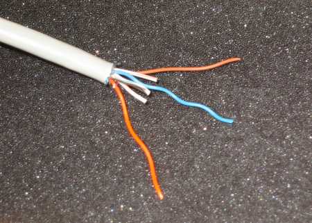
Step 2.
Assuming that your shield both has metal foil and a thin ground
wire bundle remove the metal foil. If you only have the metal foil you will
have to somehow connect a short wire to this shield.
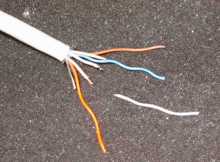
Cut off the green/green-white
twisted pair.
The other 3 pairs are untwisted and the white pairs are cut
to a length of round 20 mm. Also the shield wire is cut to 20 mm.
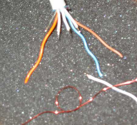
Step 3.
Remove the isolation from the 3 short wires.
Additionally take
the green-white wire you just cut off and remove the isolation from the tip
in one end.
Step 4.
Time to use the soldering iron.
First put some solder on all
4 wires and the ground wire.
We are now going to solder all 5 wires together.
It is almost impossible to hold 5 wires together at the same time.
With a
small copper wire or sewing thread make a small simple knot like shown.
Step 5.
Tie the 4 wires together with the copper wire so that all 4 tips
touch each other.
Step 6.
You can now easily heat the wires holding the soldering iron in
one hand and holding the 5th small loose wire in the other hand. Because you
already have put solder on the tip of all wires it is a simple matter of heating
up the solder so it all melts together.
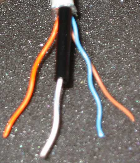
Step 7.
You can now remove the copper wire and put some isolation tape
or heat shrink tube round the solder joint to isolate it.
Step 8.
We now need to put the 4 wires into the modular 6P4C connector
(6 positions/4 contacts - also known as RJ11). The connector is the same as
you use for all sorts of telephone equipment. You can also use a 6P6C (6 positions/6
contacts) but then you have to take care to put the wires in the 4 center pins.
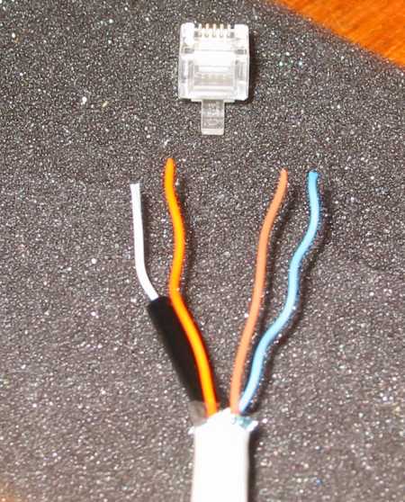
Place
the 4 wires as shown. The 6P4C is shown from where the cable goes in and the
lock pin down.
From left to right: Ground (white), orange, brown and blue.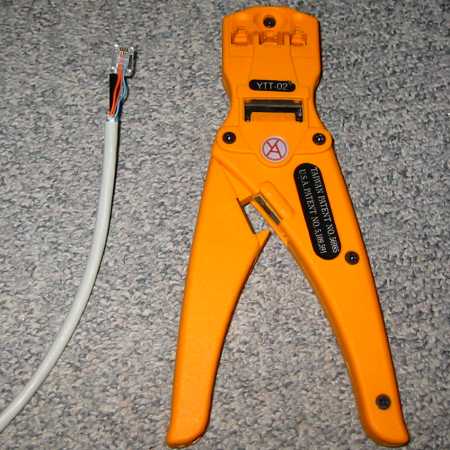
Step 9.
Carefully press the four wires all the way in maintaining the
right sequence.
With a special tool made for modular (RJ) connectors press
the connector pins in. If you do not have such a tool then you must go out and
either borrow or buy it. If you are smart you buy one that also fits the
8P8C (RJ45) type. Then you can make your own computer network cables for ethernet.
It takes only a few cables and the cost of the tool is saved. You do not need
to invest in an expensive model since you will only be using it rarely. They
all do the job satisfactory. The expensive professional types are just nice
to use and last longer.
Since the outside isolation of the cable is not inside
the connector the strain relief is not ideal. The wires are only held by the
contacts, so it may be a good idea to support the cable with a tie wrap or similar
when you plug finally plug it into the outdoor temperature/humidity sensor.
Step 10.
Now we need to modify the wind sensor end. This is a bit more
difficult. There is the nice way and there is the easier and faster way. I chose
the nice but difficult way. Richard Huntington (New Zealand) used the simpler
and easier way and both ways are confirmed to be working. I would recommend
the easier way unless you are used to soldering on PCBs. I will show both methods.
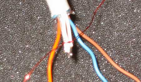
First
the difficult way:
Take the wind sensor apart. You will need to remove the
wind mill. It is held by one small screw. When this screw is removed you can
pull off the mill.
Then you open the wind sensor housing. This is done by
removing the 3 visible screws.
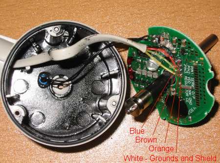
Carefully take the housing apart. Try and
get familiar with how the wire is routed. The picture above shown how it looks
like before the modification. I forgot to take a picture after.
You now remove
the existing 4 wire cable by unsoldering it from the PCB.
Remove the old
solder and put a little fresh solder on each of the 4 pads. Not too much.
You
now prepare the other end of the STP cable the same way you did in steps 1 to
7. You may want to make the wires a little bit longer so that the grounding
connection is done right where the cable enters the wind sensor housing. I do
not recommend trying to solder 3 wires and a shield to one pad on the PCB. Join
them in one connection point and then route one single wire to the ground pad
on the PCB.
Make sure to put the new cable through the wind sensor holder
before putting it into the wind sensor housing. Otherwise you have to pull maybe
10 m of thick STP cable through the holder afterwards.
Now it is time to
put it all back together again.
OK here comes the easier method.
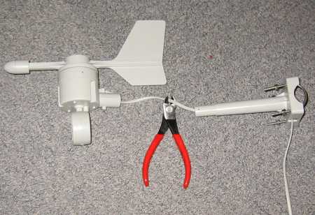
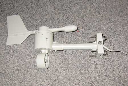
Step 11.
Remove the wind sensor holder or bracket (the thing on the right)
from the sensor.
Cut the wire approx as shown. Close enough to the wind sensor
to make sure that the connection point is inside the plastic tube of the holder.
And far enough to make sure that you can cut away an extra piece if it does
not work out for you the first time.
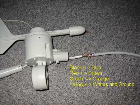
Step 12.
Again make the same preparation of the STP cable as you did in
the other end.
Remove the foil.
Remove the unused green/green-white pair.
Join
all the white wires and the ground shield in one solder joint using a small
copper wire to hold them together while you solder.
One difference is that
this time you cut all wires to the same length.
The wire from the wind sensor
also needs to be un-isolated.
For all wires add some solder to each tip using
the soldering iron and some fresh solder (never used the old solder that has
been on the tip for minutes).
If you isolate each wire connection with heat
shrink tubes NOW it the time to add them to the 4 wires PLUS the thicker piece
on the cable as well. You know you hate yourself when you forget and have to
do it all over again. If you use isolation tape you can wrap it around after
you have soldered.
Carefully solder the 4 wires together making sure you
get a good connection. By adding solder to the tip of all the wires before you
join them it is very easy to put them together with one hand and holding the
soldering iron with the other hand. You will normally not need to add more solder.
If you do not pre-solder the wire ends you will need a third hand to hold and
apply the solder.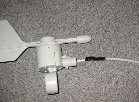
Step 13.
When the soldering is done you can remove the copper wire you
used to hold the ground wires together.
Now isolate each wire with tape or
heat shrink tubes. Make sure that the wires are isolated from each other.
Then
add some isolation round the entire cable to prevent humidity from getting into
the cable.
Step 14.
Push the holder into the wind sensor housing again.
You are done. All that is left is testing it. If it does not work I bet you have mirrored the wires. If you have done it wrong inside the wind sensor you must open it again and correct it. The ground must be connected to the shield and the ground pairs for the shielding to work. If you mirrored at the modular connector then you can just cut the connector off and put another the right way.
I have used round 11 m of wire but it should work maybe up to 30 m of wire.
Before I made the modification, I saw the 25.5 m/s reading 2-10
times per day. Sometimes even more. If I used a radio link instead of cable
connection I would get the false reading 1-3 times pr day. This is simply due
to the fact that the wind sensor is read less often when using radio link.
As
I write this I have not seen one single 25.5 m/s reading for more than 3 days (update: Dec 2004 - and also after more than one year)
and I run with the wire link. I am now much more happy with my weather station
since the max wind speed and min wind chill data can now be used.
Good luck.
Kenneth Lavrsen
2003 October 24.
[Weather Index] [Weather Station] [Weather Graphs] [World Weather] [Kenneth's Homepage]